A heat engine is a system that uses energy in the form of heat and transforms it into mechanical work, then exhausts the waste heat. This process often involves Waste Heat Recovery, where exhaust heat is harnessed for additional efficiency. It operates by bringing a working substance from a higher temperature state to a lower temperature state.
Essentially, it converts the flow of thermal energy into useful mechanical work by maintaining heat flow between a hot reservoir and a cold reservoir within the engine.
Three processes occur in every heat engine. The mechanical work is produced by converting thermal energy into mechanical energy. The heat engine firstly converts thermal energy into chemical energy [fuel], then mechanical work. By using the relationship between the operating temperatures of the engine, the efficiency can be obtained easily.
A working substance is a material often a fluid like a gas or liquid, that performs mechanical work in a thermodynamic system. By under going changes in temperature , pressure and volume as it absorbs heat and then release it converting thermal energy into useful work.(e.g Steam in a steam engine , air in a gas turbine) The most efficient heat engine cycle is the Carnot cycle, consisting of two isothermal processes and two adiabatic processes.
Internal combustion engines operate based on fundamental thermodynamic processes. Understanding these is key to mastering the Otto, Diesel, and Dual Cycles.
W = PΔV
W = 0
Q = W
Q = 0
In the Diesel Cycle, heat addition is Isobaric, while in the Otto Cycle, it is Isochoric.
One of the important implications of the first law of thermodynamics is that machines can be harnessed to do work that humans previously did by hand or by external energy supplies such as running water or the heat of the Sun. A machine that uses heat transfer to do work is known as a heat engine. There are several simple processes, used by heat engines, that flow from the first law of thermodynamics. Among them are the isobaric, isochoric, isothermal and adiabatic processes. These processes differ from one another based on how they affect pressure , volume, temperature and heat transfer.
Within these engines, several key processes occur that flow directly from the First Law. These include Isobaric, Isochoric, Isothermal, and Adiabatic processes.
Key Takeaway: Each of these processes is unique in how it affects the core thermodynamic variables: Pressure, Volume, Temperature, and Heat Transfer. Mastering these relationships is the foundation of marine engineering efficiency.
Internal combustion engine works mostly on once of the three cycle namely Otto cycle, Diesel cycle and Dual cycle.
Otto cycle is considered as the ideal cycle for petrol or spark ignition engine. In this cycle heat addition is at constant volume.
Diesel cycle is considered as ideal cycle for diesel engine or compression ignition engine. In this cycle heat addition is at constant pressure.
A dual cycle engine consists(ပါဝင်သည်) of four main processes: intake, compression, combustion and expansion. During intake, air is drawn into the cylinder through a valve. During compression, the piston moves up and compresses the air, rising its temperature and pressure. During combustion, fuel is injected into the cylinder at a constant pressure, igniting the air-fuel mixture and further increasing the temperature and pressure. During expansion, the piston moves down and converts the thermal energy into mechanical work, lowering the temperature and pressure. The exhaust valve then opens and the burned gases are released.
A cycle is a series of separate events which are essential for the efficient operation of an engine.
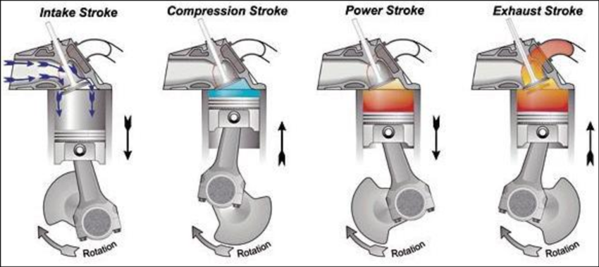
The four-stroke cycle is completed in four strokes of the piston, or two revolutions of the crankshaft (two cycles, one power). In order to 
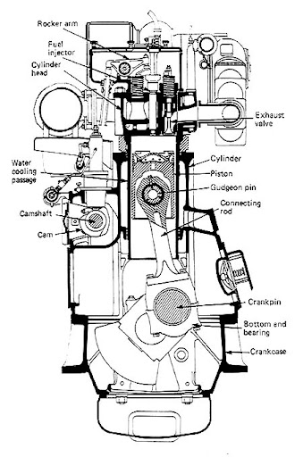
operate this cycle, the engine requires a mechanism. A cross-section of a four-stroke cycle engine is shown in the diagram.
The engine is made up of a trunk type piston which moves up and down in a cylinder which is covered at the top by a cylinder head. The fuel injector, through which fuel enters the cylinder, is located in the cylinder head. The inlet and exhaust valves are also housed in the cylinder head and held shut by springs (စပရိန်များဖြင့် ပိတ်ထားသည်)။
The piston is joined to the connecting rod by a gudgeon pin. The
bottom end or big end of the connecting rod is joined to the
crankpin which forms part of the crankshaft. With this assembly,
the linear up and down movement of the piston is converted into
rotary movement of the crankshaft.
ဤစုစည်းမှုဖြင့် piston ၏ မျဉ်းဖြောင့်အတိုင်း အပေါ်အောက်
ရွေ့လျားမှုကို crankshaft ၏ လည်ပတ်ရွေ့လျားမှုအဖြစ်သို့
ပြောင်းလဲပေးသည်။
The name “Trunk Piston” refers to the piston skirt or trunk. The purpose of the skirt or trunk in four-stroke cycle engines is to act in a similar manner to a crosshead. It takes the thrust caused by connecting-rod angularity (ထောင့်မှန်ကျမှု) and transmits it to the side of the cylinder liner, in the same way as the crosshead slipper transmits the thrust to the crosshead guide.
With such engines, which are termed trunk-piston engines, the engine height is considerably (သိသိသာသာ) reduced compared with that of a crosshead engine of similar power and speed. The engine-manufacturing costs are also reduced. It means of course that there is no separation between the crankcase and the liner and piston. This has its disadvantages, especially when considering the choice of lubricating oils when burning high sulphur residual fuels.
The crankshaft is arranged to drive through gears the camshaft, which either directly or through pushrods operates rocker arms which open the inlet and exhaust valves. The crankshaft is ‘timed’ to open the valves at the correct point in the cycle. The crankshaft is surrounded by the crankcase and the engine framework which supports the cylinders and houses the crankshaft bearings. The cylinder and cylinder head are arranged with water-cooling passages around them.
The diagrams indicating simultaneously (တပြိုင်နက်တည်း ညွှန်ပြသည်။) the pressure and the relative position of the piston in the cylinder are known as indicator diagrams.
In phase with piston movement, with “fuel on”, to determine indicated power. P.max (between atmospheric line and highest point), operational fault.
90deg. Out of phase with piston movement, with “fuel on”, to determine: P.max, P.com, nature of expansion curve. To evaluate injection, ignition delay, fuel quality, combustion, loss of compression, expansion process, fuel pump timing and after burning.
In phase and “fuel cut off”, to determine: Compression pressure and cylinder tightness.
In phase, using light spring, with “fuel on”, to determine: Pressure variation during exhaust and scavenging periods.
P.max = maximum combustion pressure (fuel on) | P.com = compression pressure (fuel on)
Note: Cetane no. Shows the ignition quality no.
Indicator Diagram တစ်ခုရဲ့ ဧရိယာ (Area) ကို သိရင် Mean Effective Pressure ကို အောက်ပါအတိုင်း ရှာနိုင်ပါတယ်။
* ပုံတွင် ပြထားသည့်အတိုင်း Area (a) ကို Planimeter ဖြင့် တိုင်းတာပြီး Pm ကို တွက်ချက်ရယူသည်။
အင်ဂျင်ဆလင်ဒါအတွင်း ဖြစ်ပေါ်လာသော Power ကို တွက်ချက်ရန် အောက်ပါ Formula ကို အသုံးပြုသည်။
P-V Diagram သည် Engine Cycle တစ်ခုလုံး၏ ဖိအားနှင့် ထုထည်ပြောင်းလဲမှုကို ပြသသည်။
The area within the diagram represents the work done per cycle:
Actual power developed in the cylinder from high-pressure gas acting on the piston.
Power available at the output shaft. (BP < IP due to friction and heat losses).
Output from reduction gears, couplings, or clutches connected to the crankshaft.
Power delivered to the propeller (accounts for shaft bearing losses).
Actual power developed by propeller revolutions and pitch angle.
Power required to drive the ship against total resistance at service speed.
Engine draws in air by piston movement. Pressure is slightly lower (အနည်းငယ်နိမ့်) than atmospheric pressure.
Air supply takes place under pressure higher than atmospheric. Supplied by an exhaust gas turbo-blower.