Principle of Refrigeration
Basic Concepts & Vapor Compression CyclePrinciples of Refrigeration
Refrigeration is based on two fundamental physical principles:
- Liquids absorb heat when changed from liquid to gas.
- Gases give off heat when changed from gas to liquid.
For an air conditioning system to operate with economy, the refrigerant must be used repeatedly. For this reason, all air conditioners use the same cycle of compression, condensation, expansion, and evaporation in a closed circuit. The same refrigerant is used to move the heat from one area to cool it, and to expel this heat in another area.
In marine engineering, this is vital for cargo preservation (Reefer ships) and air conditioning systems. It follows the Second Law of Thermodynamics, which states that heat cannot spontaneously flow from a cold body to a hot body without external work.
Basic Refrigeration Cycle Operation
The cycle moves heat using four main components in a continuous loop:
Exam Prep Question
"Describe the operation of a basic refrigeration cycle, stating clearly the functions of the compressor, condenser, expansion valve, and evaporator.” (Or) “Can you explain how the basic refrigeration cycle works and what each major component does?"
Sample Answer:
The basic refrigeration cycle moves heat using four main components: compressor, condenser, expansion valve, and evaporator. It continuously cycles a refrigerant to cool a space by absorbing heat in the evaporator and releasing it elsewhere in the condenser.
A low-pressure vapor enters the compressor, becoming a hot, high-pressure gas; it then cools and liquefies in the condenser, releases heat, moves through the expansion valve (dropping pressure/temp), and finally absorbs heat in the evaporator, turning back into a vapor to repeat the cycle.
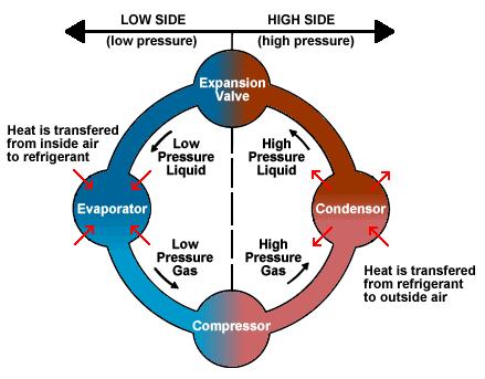
Cycle Operation
The cycle moves heat using four main components in a continuous loop:
- 1. Compression: Low-pressure gas enters the compressor and is discharged as hot, high-pressure gas.
- 2. Condensation: High-pressure gas liquefies in the condenser, releasing heat to the cooling medium.
- 3. Expansion: High-pressure liquid passes through the expansion valve, dropping its pressure and temperature.
- 4. Evaporation: Low-pressure liquid absorbs heat in the evaporator, turning back into a gas.
Evaporator (အရည်အအေးခန်း)
The low pressure liquid refrigerant, after passing through the expansion valve, expands. It takes in heat from the surrounding and evaporates. The gas is then sucked up by the compressor.
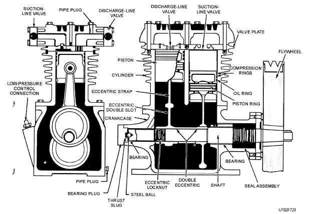
Compressor
Reciprocating (အပြန်အလှန်) single or two stage compressor is commonly used for compressing and supplying the refrigerant to the system.
Two types of compressor:
- Open type
- Semi-hermetic type
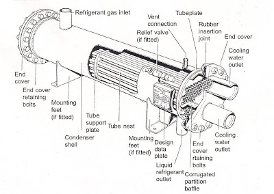
Condenser & Liquid Receiver
The hot compressed gas is passed through a condenser where it cools down and liquefies. The resulting liquid is then stored in the Liquid Receiver.
Engineering Insight: Pump Down
The receiver is essential for maintenance. It is used to collect and store the refrigerant (Gas collect) when major repair work needs to be performed on the system.
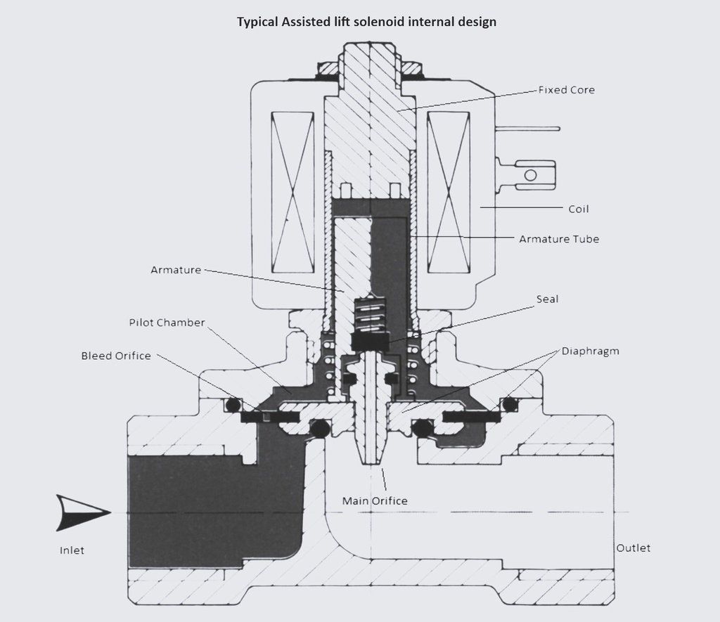
Thermostatic Expansion Valve (T.E.V)
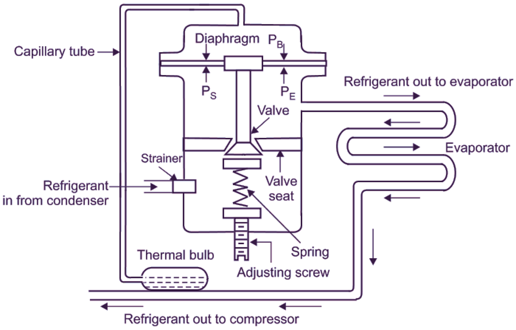
Working Principle
Thermostatic valve regulate (ထိန်းညှိပေးသည်။) the flow of the refrigerant in to the room to maintain the temperature of the room. For this the expansion valve is controlled by a diaphragm movement due to the pressure variation which is operated by the bulb sensor (thermal sensor) filled with expandable fluid fitted at the evaporator outlet.
T.E.V Function (၂ မှတ်တန်)
The thermostatic expansion valve supplies the correct amount of refrigerant to evaporators where the refrigerants takes up (absorb) the heat from the room and boils off (hot water) into vapors resulting in temperature drop for that room.
Pro-Tips for Oral Exam
- P1 = Bulb Pressure (Opening Force)
- P2 = Evaporator Pressure (Closing Force)
- Ps = Spring Pressure (Closing Force)
Filter Drier
The system is fitted with a liquid line filter drier consisting of a cylinder and renewable cartridges filled with activated alumina or silica-gel. The desiccant substance has microscopic holes for the liquid refrigerant to pass through.
Liquid Sight Glass
A sight glass/moisture indicator assembly used as a diagnostic and system condition monitoring device. It checks liquid lines for evidence of vapor, moisture content, and refrigerant flow condition.
Refrigeration Pressure Switches (LP & HP)
Low Pressure (LP) Cut-off
A compressor safety that cuts off the compressor during a pressure drop in the suction line. When pressure falls below the set value (room cooled), the LP switch auto-trips the compressor. It restarts automatically when pressure rises due to room temperature increase.
High Pressure (HP) Cut-out
Activates and trips the compressor when discharge pressure exceeds the limit. Crucial: This is NOT auto-reset; it must be reset manually for safety reasons.
Solenoid Valves Control
Master Solenoid Valve
Fitted in the main line after the condenser discharge. It closes when the compressor stops to prevent refrigerant overflow into the evaporator.
Individual Room Solenoids
Each room/hold is fitted with an individual solenoid valve to precisely control the refrigerant flow to that specific area.
Refrigeration Compressor
The compressor is the heart of the system, responsible for compressing low-pressure refrigerant gas into high-pressure, high-temperature gas to be sent to the condenser.
Oil Separator
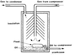
After the oil-refrigerant mixture leaves the compressor, it enters the oil separator. As it passes through filters and baffles, the clean oil drops to the bottom while the gas refrigerant is discharged into the condenser.
Condenser (Heat Exchanger)
The condenser removes heat from the high-pressure refrigerant gas, causing it to condense into a high-pressure liquid. Cooling is typically achieved by water or air passing through the tubes/fins.
Safety Relief Valves
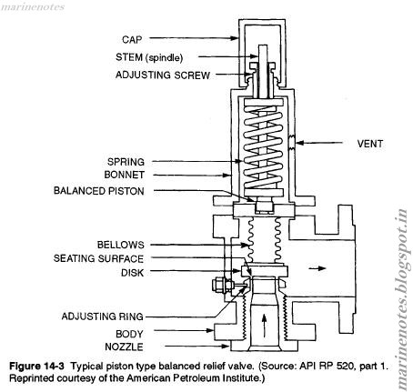
Compressor Protection
Relief valves are fitted on the discharge side of the compressor. They will lift and safeguard the compressor in the event of over-pressure.
Condenser Protection
One relief valve is also fitted in the condenser to avoid damage if there is high pressure in the discharge line.
Crankcase Oil Heater
An Oil heater is provided for the compressor crankcase oil. It prevents the compressor from getting excessively cold, which may affect the lubrication of moving parts.
Refrigerant Types & Impact
Ozone Layer ကို ပျက်စီးစေလို့ အခုဆိုရင် အသုံးမပြုတော့ဘဲ ရပ်ဆိုင်းထားပါပြီ (Phased out)။
Ozone ကို မထိခိုက်ပေမယ့် Global Warming (ကမ္ဘာကြီးပူနွေးမှု) ကို ဖြစ်စေနိုင်ပါတယ်။
Objectives of AC on Ships
- To extract excess heat.
- To raise air temperature when required.
- To add or reduce moisture content (Humidity control).
- To maintain sufficient air flow and movement.
- To remove dust and filter the air.
What is a Refrigerant?
A refrigerant is a chemical substance used in refrigeration and air conditioning systems. They work by absorbing heat and transferring it in a cycle to achieve cooling of air or objects.
Refrigerants typically have low boiling points, allowing them to evaporate and cool the surrounding environment at relatively low temperatures. When in liquid state, the refrigerant absorbs heat and evaporates into a gas. Then, through compression and condensation processes, the refrigerant releases heat and returns to a liquid state.
Types of AC Refrigerants
Chlorofluorocarbons (Phased out due to ozone layer damage)
Hydrochlorofluorocarbon (Phased out due to ozone layer damage)
Hydrofluorocarbon (e.g., R-410A, R-134a, R-407C). Widely used today; contributes to global warming.
Air Handling & System Flow
- Air Handling Unit (AHU): Contains the evaporator coil which extracts the heat from the air inside.
- Compressor: Draws low pressure refrigerant vapor and delivers high pressure vapor through an oil separator to the condenser.
- Condenser: Liquefies the refrigerant.
- Flow Sequence: Condenser → Master Solenoid → Filter Dryer → TEV → AHU.
Objectives of Air Conditioning on Ships
Purpose: Treating air to control simultaneously its temperature, humidity, cleanliness, and distribution.